
Digtophone (CruftFest 2015)
- Nov 17, 2015
- 4 min read
Digtophone: a dictation machine digitally hacked to process the incoming sounds, with the objective to create an interactive ludic audio interface.
Outline.
I built this device as my CruftFest project by hacking an Olympus Pearlcorder. The objective was to create a hybrid (computer + cruft) interactive sound interface, that would allow users to generate specific soundscapes with their voice.
Hence, Digtophone enables pitch shifting, a stutter effect, and a delay effect that repeats the sound as a bizarre and decaying echo. It also encompasses sound processing to create a machine, sci-fi like soundscape. Finally, it allows to record messages and play them back again.

Classified as a ludic interface, the chore idea is that the user will see an ordinary Dictation Machine on the outside, and get surprised when using it in a ludic way. Therefore, its main target is fun, creativity, and audio experimentation.
Behind the Digtophone.
Digtophone was born under the form of a Pearlcorder S713, manufactured by Olympus Corporation. It was a microcassette recorder that contained a built-in stereo microphone, a dynamic speaker, dual recording speeds (2.4 and 1.2) to choose between longer recordings and better sound quality, hands-free activation by sound, and fast playback modes.
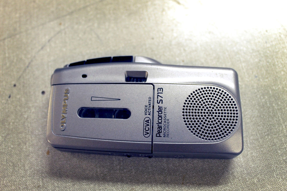
Digtophone is a hacked Olympus Pearlcorder built with:
1 Arduino microcontroller.
1 CCTV add-on audio module that includes an electret microphone with amplification, providing 20 to 160,000 Hz.
1 6.35 mm male audio jack.
4 10k Ω potentiometers as audio controllers for input and output sound.
1 mini breadboard.
1 Alesis IO2 usb audio interface (can be any usb audio interface).
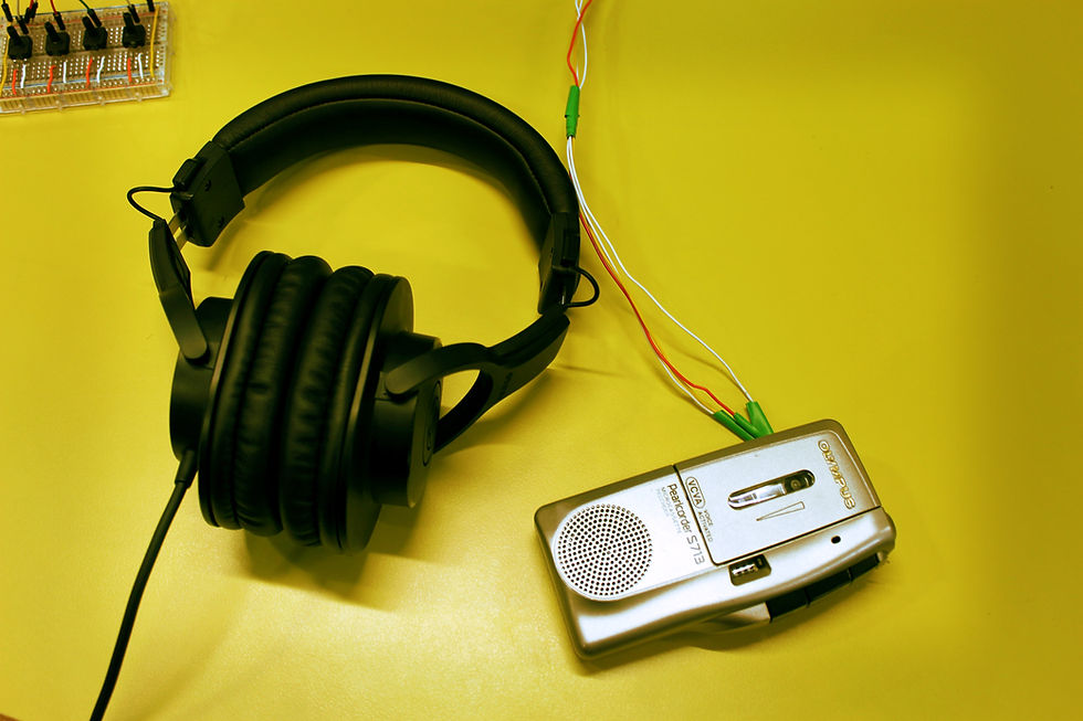
Wiring up.
The CCTV add-on audio module connects: ground (black wire) and audio out (white wire) to the 6.35 mm audio jack; and ground (black) and DC 12 V (red) to the Arduino power pins.
The Pearlcorder's original circuit board was removed to give space to the new audio-module.
The audio jack is connected to the microphone input of Alesis IO2 usb audio interface.
Alesis IO2 is connected to the computer, where Max/MXP patch is running: live processing of sound.
Four 10k Ω potentiometers are attached to a mini breadboard. Each of them is connected to the Arduino’s 5 volts and ground pins, as well as connected to 4 analog IO pins.
Arduino is connected to the computer as well, through its usb port.

Programming.
The arduino code is in charge to detect the potentiometers attached to the mini breadboard, and send their information to the serial port. This enables the connection between the physical potentiometers and the Max/MSP patch later on.
The Max/MSP patch makes the magic happen! It processes the audio in real time. It includes Pitch shift, Stutter, Delay, a Soundscape processing and a Buffer to record the messages and playback. A toggle activates the serial port reading, to enable communication between the external controllers and the patch.
The Pitch shifter effect works with a phasor that expands or contracts the sound waves, creating high or low pitches in the incoming sounds. It has two phasors, slightly apart from each other, to avoid a nasty click in the sound when only one is being used.
The Delay effect works with a delay object to create a repeating and decaying effect of the sound.
The Stutter effect creates repetitions of the sounds. Tapin and tapout store the sound and repeat some fragments of it.
The Soundscape processing was added to give some distorted sound to add more ludic instruments for the user. It takes the incoming sound and divides it in bands; one of them is processed and turned into the resulting sound.
Buffer, Record and Play options are the remains of what one time was a recording machine. The buffer stores the incoming sound, which can be recorded up to one minute (to avoid the software to crash at some point) and then can be played back.


Digto-challenges.
Coming from a Performing Arts background, this project was a big challenge for me. When I started, I did not know anything about how to do the physical part and I had never used Max in the past. I solved most of my problems thanks to a deep research and the lecturer orientation.
During the CruftFest, people was able to enjoy a good time playing with the audio processing of their voices in real-time. Some of the effects were very surprising and, most of all, fun. Depending if the are (or not) a sound person, users needed some time to familiarize with the hybrid interfase, after what they could hear some interesting feedback coming from the Digtophone, which was classed as fun, extrange, noisy or evilish.
Result.
This was my first time creating any kind electronic interface and, in conclusion, this was enriching an interesting, but most of all challenging and stressful. CruftFest showed me that anything we can imagine is possible to be created, but we need the knowledge and/or where to look for the right answers. In this behalf, lecturers, assistant teachers and classmates were extremely helpful with all my questions.
Special credit and thanks to:
Andrew McPherson, lecturer of the IDMT module for the MAT PhD, Queen Mary University of London.
Martin Prosser, who donated the original Olympus Pearlcorder.
Jason Safir’s http://www.underwater.ca/blog/arduino-to-max-msp/
https://www.youtube.com/watch?v=uyzY_ZP54pA and https://www.youtube.com/watch?v=4G3mFBj1UZA
Murizio Giri's https://www.youtube.com/watch?v=PtL8vjYyAm8
Joel Rich's https://www.youtube.com/watch?v=LoA0a-zFC8c
Edo Paulus' https://www.youtube.com/watch?v=tAtYht4QVnA


Comments